Below is a build-plan that was shared by club member Russ Hamilton (VE7RWX).
It is a 14-gauge fan-dipole that he has made, tested and found to be a good project. He indicates it can be made in an afternoon and it’s based on one in the ARRL Antenna Handbook. It can be modified to cover other bands, but built as described, it will work on 20 – 17 – 15 – 12 and possibly 10m bands.
The antenna works best with an optional 1:1 torroidal current balun enclosed in some type (your choice) of plastic box, which is sealed except for a small drain hole on the bottom to allow any condensation to escape.
Russ chose a round or octagonal electrical box available at Home Depot or Revy. That allowed using the box’s mounting holes as a partial strain relief for the wires as they exited the box, and are under tension when the antenna is up in the air.
The design for the optional 1:1 balun can be found on numerous online sites and is beyond the antenna build description here.
This antenna design uses 2-strips of 8ft plastic ceramic tile trim, cut to 40 cm (16”) long pieces, placed on each antenna side to separate the wires. (see photos)
The antenna wires are spaced at approximately 4 inches from each other vertically on the separators, and affixed to them using zap straps.
Use approximately even spacing between the wire separators.
Separators should also be located at the ends of each Band’s wire length, to allow a piece of tensioning paracord to be attached at that point.
Materials:
- 30m – (100ft) insulated 14 Gauge wire
- 2 – 8ft lengths of 3/8 inch plastic tile edging
- 1 – pkg 6 to 8 inch long zap straps (50)
- 2 – Lengths of rope to hoist up the antenna on each end
- 2 – Bungee cords or rubber tie-down straps, for tensioning , one at each end
- 1 – pkg (25ft) of paracord
Each antenna wire length given is for ONE HALF of the antenna – this is for ONE side only of the dipole!
Cut the length of each wire, adding enough extra to allow for adjustments. (add about 10cm+ to each )
From top to bottom order with horizontal orientation of the antenna – wire length:
Top Wire 1 – 20m Band – 446cm +/- 5cm (every 1 cm moves the resonance about +/- 50KHz)
Upper Wire 2 – 17m Band – 368cm +/- 5cm
Lower Wire 3 – 15m Band – 324cm +/- 5cm (every 1 cm moves the resonance about +/- 40 KHz)
Bottom Wire 4 – 12m Band – 280cm +/- 5cm
NOTE: These values will get you CLOSE to resonance in the middle of each band, above about a 12 ft antenna height.
Construction variables will mean you have to adjust to get an exact resonance at a particular frequency within each band. Trial and error method.
Russ notes that he is particular about his SWR, which caused him to be picky and adjust up or down in 1 cm or so increments using an antenna analyzer until close to what he wanted.
You can calculate the change in length needed, for a change in resonant frequency desired, using a simple ratio formula:
Length 1 (starting) = L1
Length 2 (desired) = L2 ß You want to know this, for the desired change in resonant frequency
Frequency 1 (starting) = F1
Frequency 2 (desired) = F2
Formula: L1 = F1 or L2 = (F2/F1) x L1 Solve for L2, to obtain the new wire length for the desired resonant frequency.
L2 F2
Cut the lengths of wire, leaving enough extra to tune the antenna. Attach to the balun, or to the ends of the coax (strain relieved).
Wrap the extra length of the ends of the wires back on each other (twisted together) to allow for adjustment, and to form a loop on the end for the tensioning paracord to easily attach. Test and adjust the wire lengths on each side, one band at a time, as evenly as you can.
RECOMMENDED: Start with the 20m Band wire (longest) and then adjust the other bands, one at a time, moving down from the top to bottom most wire.
The tricky part is getting the paracord adjustment right so that the ends of each wire (on each side) are tensioned roughly equally, to hold the wires straight.
Russ used a single length of paracord attached to one end to the supporting antenna anchor point, at the end of the top 20m wire and the support rope, then wrapping the paracord cord once around through other separators, where the ends of the other band wires were, ending at the bottom wire. This allowed the overall paracord length to be “tensioned” to easily adjust the middle wire tensions by “sliding” the paracord back and forth on the separators. Other methods to keep the wires tight are also possible.
Russ reports that it’s not pretty, but it is functional!
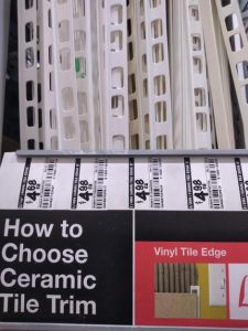 Separator material at Home Depot.
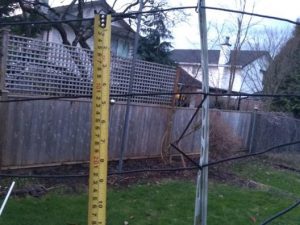 Spacing of each wire.
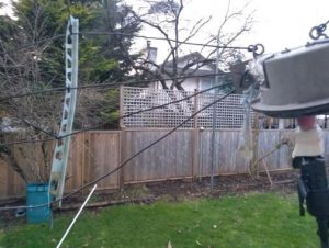 Photo showing how wires spread out from balun/coax unit.
![]() Paracord on spacers for tensioning. Spacer at end of band wire.
Paracord on spacers for tensioning. Spacer at end of band wire.
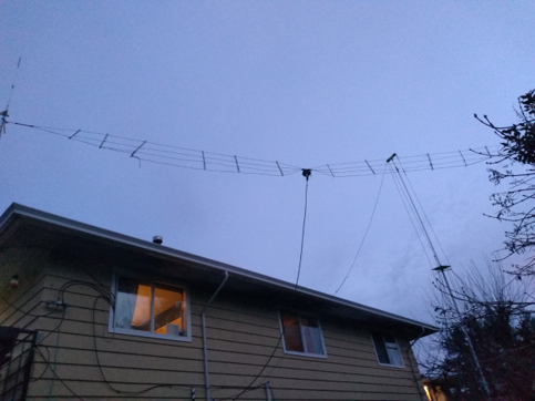
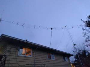 Final product in the air.
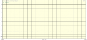
Test results
Russ mounted his antenna about 25 feet up for the SWR measurements. Ideally, you want to be up about 0.6 of a wavelength at lowest frequency of interest. So, for 20M this is about 12M high, or 40ft.
For most, this may be a bit unrealistic, so a compromise of 25 feet or so (height of roof of a 2-storey house), gets us up at 7.5m, which is good enough. (Half a wavelength on 15m)
As you can see, the antenna overall is optimized for use on 20M band, the one which seems open most of the time. Although not planned for, it can be used across the entire 10M band, with a tuner.
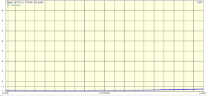 20m band
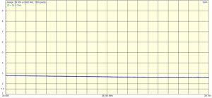
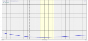 17m band
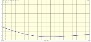 15m band
 12m band
 10m band